

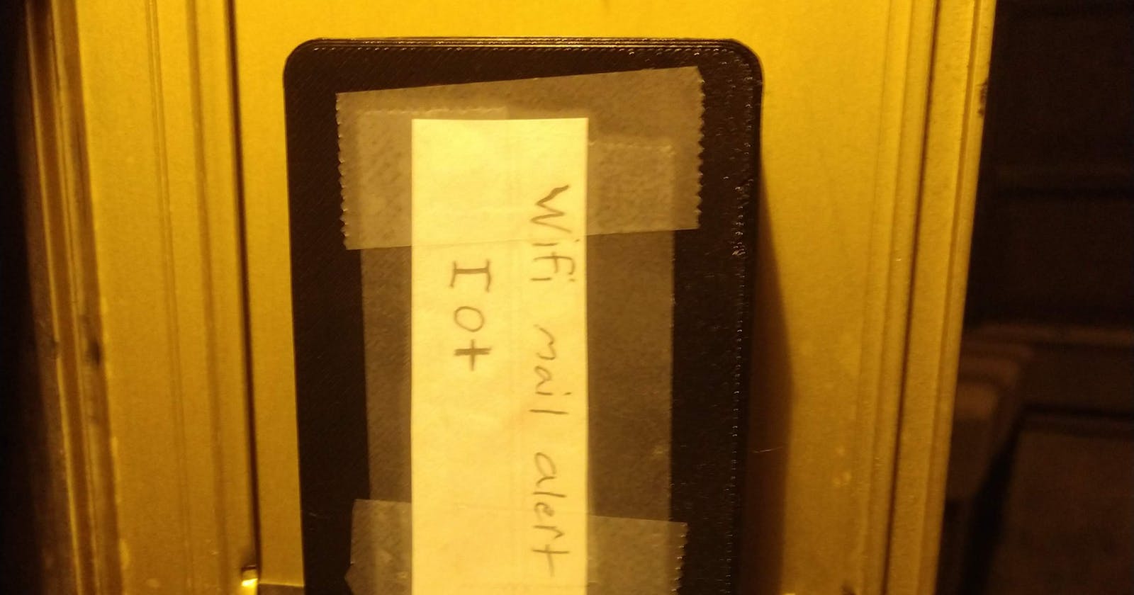

A wifi-enabled motion sensor that can last up to 600 days off of two AA batteries.
Background
The mailbox for my apartment is in an odd place, and I never check it. This leads to the mailbox becoming full and failure for mail to be delivered. The simplest solution is to just check the mailbox more often. However, I wanted to test my skills and build a device that could notify me when new mail is delivered. In fact, I have plenty of background experience with wifi-enabled microcontrollers and a motion processing unit. The challenge for me will be power delivery or management in a remote environment. This is a perfect project for me.
Hardware
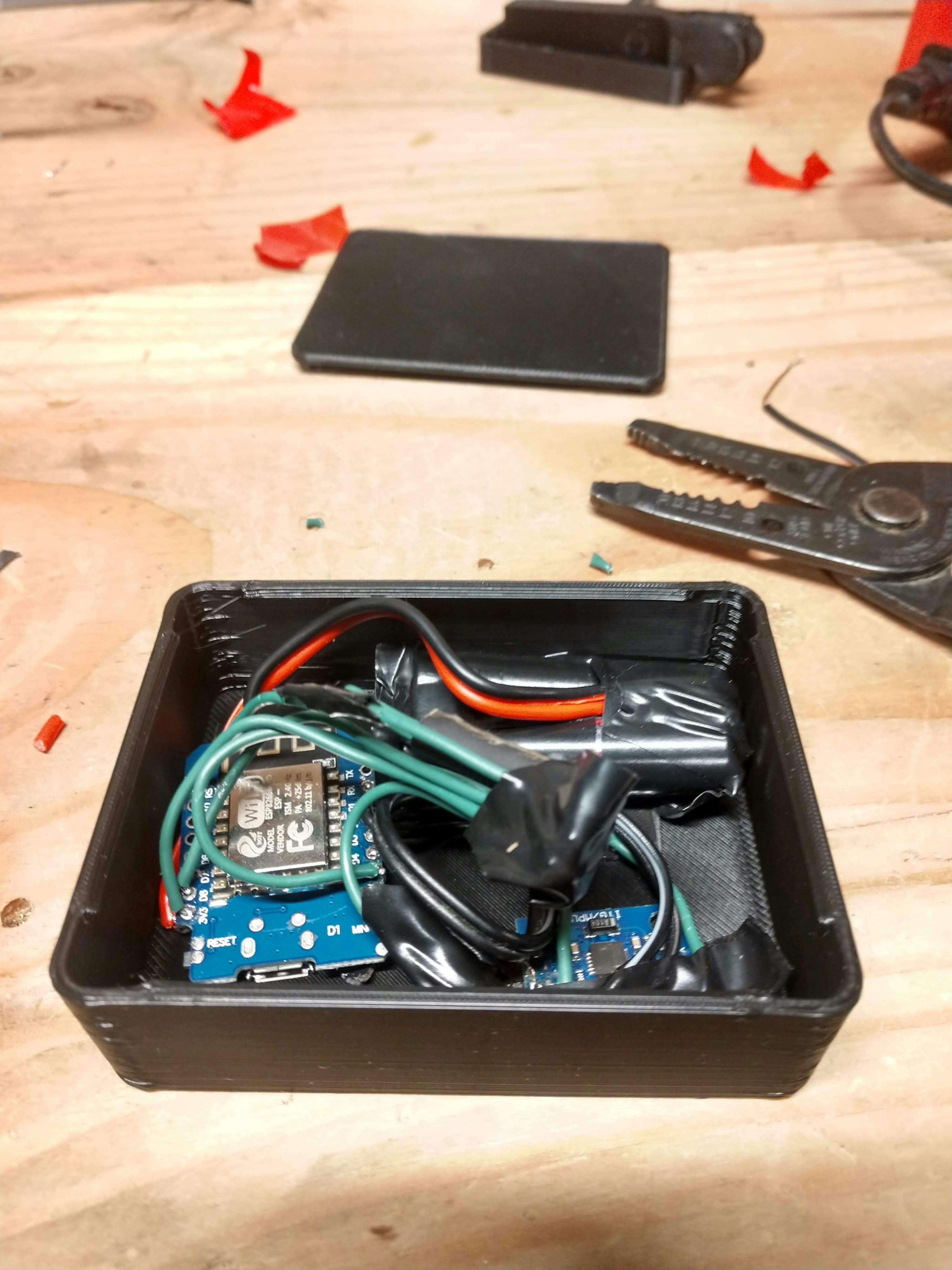
Esp8266
A wifi-enabled microcontroller that is supported by the Arduino platform. It has gpio, low-power deep sleep, and wifi.
MPU6050
This sensor measures acceleration and angles, using an accelerometer and gyroscope. It has a "Digital Motion Processing" Unit. It has its own brain called a "Digital Motion Processing" Unit. It can take some of the processing weight off the Esp8266 while using less power.
Wiring
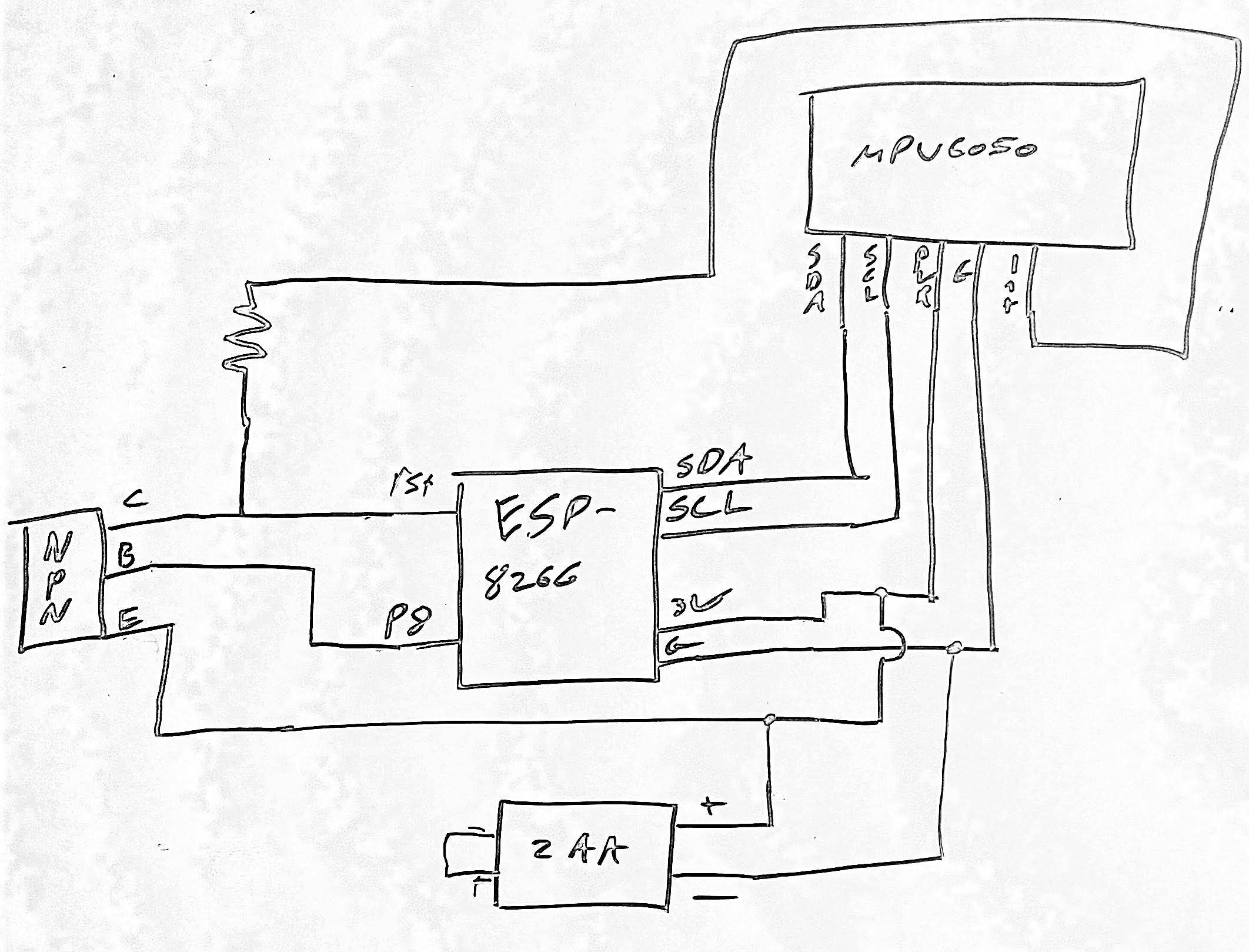
- The Esp8266 connects to the MPU6050 via I2C.
- ESP pins 1, 2 are connected to the MPU's SDA and SCL lines.
- An interrupt pin from the MPU is connected to pin 8 on the ESP.
- This is how the MPU communicates that it has new data available to be read via I2c.
- This interrupt can be programmed to be triggered in certain events such as motion patterns, or thresholds met.
- The built-in digital motion processor is used to monitor and analyze motion, and sound interrupt signals.
All pins for the ESP8266 are Wemos D1 mini mappings. For example, in code, pin 7 is actually 13. Here is a table for conversion: chewett.co.uk/blog/1066/pin-numbering-for-w..
The MPU interrupt pin will be connected to the ESP's reset pin after debugging and testing is complete. This will wake up the ESP from a deep sleep.
A setback
Context: The MPU6050 interrupt pin default state(High or Low) can be programmed after power on. Unlike the MPU6050, the Esp8266's reset pin is hardware-based. When the reset pin is pulled low, the board is reset. This can not be changed or disabled.
After some investigation, I found out the MPU6050 initialization sequence triggers the interrupt pin to send an interrupt. Before the MPU6050 can be configured to the desired state, the startup interrupt resets the ESP8266. Having the interrupt reset the ESP8266 is the desired effect. However, it is happening to soon and preventing the ESP8266 from it's required tasks. In short, an endless loop is occurring because of an unexpected interrupt signal. The Esp8266 starts, then the ESP initializes the MPU6050, the unwanted interrupt resets the ESP, and the cycle repeats.
The correct sequence is:
- Esp8266 powers on
- Send API call to trigger mail alert
- Initialize MPU6050
- Set motion trigger
- Enter deep sleep
- Motion Reset Esp8266 (repeat from step 1)
What is happening:
- Esp8266 powers on
- Send API call to trigger mail alert
- Initialize MPU6050
- RESET {repeat from step 1}
Possible solutions:
A second low-powered microcontroller(maybe an ATTiny85) can handle and filter signals from the MPU6050. While this would work, it would increase power consumption, design complexity, and overall cost.
Another option could utilize an NPN transistor. The Esp8266 reset pin just needs to be held high to prevent it from resetting. An NPN transistor, a resistor, and an additional gpio pin can be used to programmatically hold the reset pin on the ESP high. This blocks the MPU's low interrupt signal. See the final circuit design section for details on wiring.
Improving the power efficiency of the MPU 6050
There is a built-in power regulator and unneeded LED in the MPU 6050. A few changes can be made to the MPU-6050 development board GY-521 to decrease its power consumption. The article below outlines the required changes in detail.
Final circuit design
Software
The logic for this device is as follows: power on, connect to the internet, send an alert (REST API call), setup the MPU6050 and a motion trigger to wake the ESP from a deep sleep when movement is detected, go into a deep sleep, wake up on trigger and start over from the beginning.
MPU6050 and ESP8266 issue
The ESP8266 was crashing each time with a runtime error. Surprisingly, the Esp8266 handles interrupts differently than other Arduino boards. This requires adding ICACHE_RAM_ATTR right before the name of the interrupt function.
I found the solution here: esp8266.com/viewtopic.php?f=11&t=20118&..
Code
#include <FS.h>
#include <arduino_mpu.h>
#include <inv_mpu.h>
#include <inv_mpu_dmp_motion_driver.h>
#include <Wire.h>
#include <DNSServer.h>
#include <ESP8266WiFi.h>
#include <ESP8266WebServer.h>
#include <WiFiManager.h>
#include <WiFiClientSecure.h>
#include <ArduinoJson.h>
#define PL(x) Serial.println(x)
#define P(x) Serial.print(x)
char* host = "";
const int httpsPort = 443;
char api_path[100];
//flag for saving data
bool shouldSaveConfig = false;
// Use web browser to view and copy
// SHA1 fingerprint of the certificate
char fingerprint[] = "";
//callback notifying us of the need to save config
void saveConfigCallback () {
Serial.println("Should save config");
shouldSaveConfig = true;
}
void ICACHE_RAM_ATTR interrupt() {
PL("Waaaaaa?");
}
void sendAlert() {
// Use WiFiClientSecure class to create TLS connection
WiFiClientSecure client;
Serial.print("connecting to ");
Serial.println(host);
Serial.printf("Using fingerprint '%s'\n", fingerprint);
client.setFingerprint(fingerprint);
if (!client.connect(host, httpsPort)) {
Serial.println("connection failed");
return;
}
String url(api_path);
Serial.print("requesting URL: ");
Serial.println(url);
client.print(String("GET ") + url + " HTTP/1.1\r\n" +
"Host: " + host + "\r\n" +
"User-Agent: BuildFailureDetectorESP8266\r\n" +
"Connection: close\r\n\r\n");
Serial.println("request sent");
while (client.connected()) {
String line = client.readStringUntil('\n');
if (line == "\r") {
Serial.println("headers received");
break;
}
}
String line = client.readStringUntil('\n');
if (line.startsWith("{\"state\":\"success\"")) {
Serial.println("esp8266/Arduino CI successfull!");
} else {
Serial.println("esp8266/Arduino CI has failed");
}
Serial.println("reply was:");
Serial.println("==========");
Serial.println(line);
Serial.println("==========");
Serial.println("closing connection");
}
void setup() {
// Ignore mpu6050 interrupt signal while init of module
pinMode(15, OUTPUT);
digitalWrite(15, HIGH);
// Debug
Serial.begin(115200);
while (!Serial);
Serial.println("mounting FS...");
if (SPIFFS.begin()) {
Serial.println("mounted file system");
if (SPIFFS.exists("/config.json")) {
//file exists, reading and loading
Serial.println("reading config file");
File configFile = SPIFFS.open("/config.json", "r");
if (configFile) {
Serial.println("opened config file");
size_t size = configFile.size();
// Allocate a buffer to store contents of the file.
std::unique_ptr<char[]> buf(new char[size]);
configFile.readBytes(buf.get(), size);
DynamicJsonDocument json(1024);
auto deserializeError = deserializeJson(json, buf.get());
serializeJson(json, Serial);
if ( ! deserializeError ) {
Serial.println("\nparsed json");
strcpy(host, json["host"]);
strcpy(api_path, json["api_path"]);
strcpy(fingerprint, json["fingerprint"]);
} else {
Serial.println("failed to load json config");
}
configFile.close();
}
}
} else {
Serial.println("failed to mount FS");
}
//end read
// The extra parameters to be configured (can be either global or just in the setup)
// After connecting, parameter.getValue() will get you the configured value
// id/name placeholder/prompt default length
WiFiManagerParameter custom_host("host", "api.github.com", host, 100);
WiFiManagerParameter custom_path("path", "/api/2v/request_here", api_path, 100);
WiFiManagerParameter custom_fingerprint("fingerprint", "hosts sha1 finger print, found under ssl cert.", fingerprint, 100);
WiFi.mode(WIFI_STA);
WiFiManager wm;
//set config save notify callback
wm.setSaveConfigCallback(saveConfigCallback);
//add all your parameters here
wm.addParameter(&custom_host);
wm.addParameter(&custom_path);
wm.addParameter(&custom_fingerprint);
bool res;
res = wm.autoConnect("snailMailAlert", "tangoWhiskey");
if (!res) {
Serial.println("Failed to connect");
// ESP.restart();
}
else {
//if you get here you have connected to the WiFi
Serial.println("connected...yeey :)");
//read updated parameters
Serial.println("connected...yeey 1:)");
strcpy(host, custom_host.getValue());
Serial.println("connected...yeey :2)");
strcpy(api_path, custom_path.getValue());
Serial.println("connected...yeey :3)");
strcpy(fingerprint, custom_fingerprint.getValue());
Serial.println("connected...yeey :4)");
if (shouldSaveConfig) {
Serial.println("saving config");
DynamicJsonDocument json(1024);
json["host"] = host;
json["api_path"] = api_path;
json["fingerprint"] = fingerprint;
File configFile = SPIFFS.open("/config.json", "w");
if (!configFile) {
Serial.println("failed to open config file for writing");
}
serializeJson(json, Serial);
serializeJson(json, configFile);
configFile.close();
//end save
}
}
// Alert user motion detected
sendAlert();
Wire.begin(); // I2C
// mpu6050 init
struct int_param_s params;
params.pin = 13;
params.cb = interrupt;
PL(mpu_init(¶ms));
// mpu6050 interrupt
PL(mpu_set_int_level(1));
// set motion trigger
PL(mpu_lp_motion_interrupt(32, 5, 5));
PL("Ready...");
delay(20);
digitalWrite(15, LOW); // turn the LED on (HIGH is the voltage level)
delay(20);
// Deep sleep, seconds does not matter as wake up pin not connected to itself
ESP.deepSleep(10E6, WAKE_RF_DEFAULT);
}
void loop() {
// Nothing to see here... 101010
}
Power consumption calculations
Budget: AA batteries have 800 milliamps total
Sleep Costs:
- Esp8266 in deep sleep: 20uA per hour
- MPU6050 in sleep: 5uA per hour
- Tolerance: 15 uA per hour
Total Sleep cost: 40uA = 0.04 milliamps per hour
Estimation of sleep length in days:
- 0.04 *24 = 0.96 milliamps per day
- 800 / 0.96 = 833 days in sleep mode
Active Operation Costs:
- Esp8266 in operations: 150 approx. milliamps per hour
- MPU6050 in operation: 5 milliamps per hour
Total Active Operation cost: 155 milliamps per hour
Per Alert Cost:
- Time per alert/wake up 5 seconds
- 155 / 60 = 2.583 milliamps per minute
- 2.583 / 60 = 0.04 milliamps per second
Total Cost Per Alert: 0.04 * 5 = 0.2 milliamps per wake up
If mail is delivered 5 days out of 7 (worst case), then 5 wakes ups per week and 20 per month. Also, 240 wake-ups per year.
0.2 * 240 = 48 milliamps per year for wake-ups
So, the math checks out. AA batteries will last more than a year.
The end
Thank you for my article. I am currently looking for an internship and or job in computer science or a related field. If you or someone you know can help, please contact me on Linkedin: linkedin.bltstack.dev.
Bye!